Promethean Tech Water Engineering
Lot 2-26, 2nd Floor, Block C,
Jalan Kajang Perdana 3,
Taman Kajang Perdana,
43000 Kajang,
Selangor, Malaysia
![]() +6010 365 7348
+6010 365 7348
![]() +6016 442 1112
+6016 442 1112
CHLORINE HEADER VALVE
There are many varieties of valves that can be used for pressurized chlorine service such as ball valves, line valves, angle vales etc. They must be compatible with pressurized chlorine which usually makes their materials of construction a carbon steel body, PTFE seals, and Monel or Hastelloy C-276 internals. Ball valves must also come with a provision for venting the cavity in the closed position to the upstream side.
The chlorine gas pressure manifold hard piping must be connected to the containers using flexible connectors. The flexible connectors have CGA-660 threaded fittings that are to be connected to chlorine valves (with a lead gasket seal) on both the container and on the hard manifold piping. The chlorine valves mounted on the manifold are typically referred to as the header valves (however, the valves on the manifold and the ton containers are typically the same). The flexible connectors are left connected directly to the manifold header valves. However, the flexible connectors must be disconnected and reconnected at the container valves every time the containers are changed. Frequently making this threaded connection creates the concern that the flexible connector may become weakened and break near this fitting. Further, if air (which contains water vapor) is allowed to enter the manifold (typically during changing containers) then this small amount of water vapor can cause major corrosion damage to the interior of the manifold.
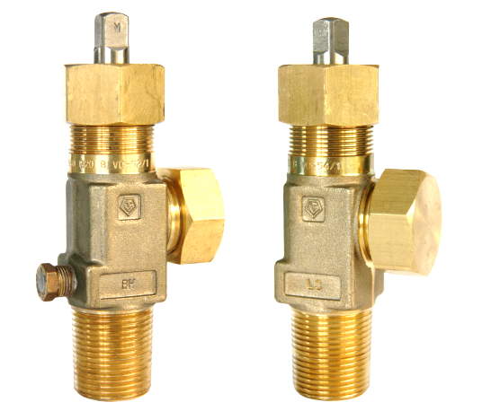
Chlorine Header Valve Maintenance SERIES CAV-06
i. Disassembly of valve
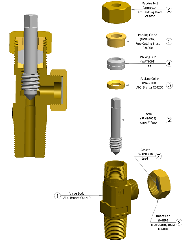
Use twisted wrench (item code – WR-EN-1) with one end having 1 1/4” open end spanner to remove outlet cap (8) & packing nut (6). Fit opposite end of the same spanner having 3/8” square size open to remove stem (2) along with other internal fitments of packing gland (5), packing (4) & packing collar (3).
ii. Cleaning of valve body & components
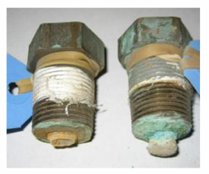
Clean valve body (1) & components observed “green”, likely Copper Chloride due moisture either in the Chlorine or which has entered the system during connections & disconnections.
The greenish layer of Copper Chloride on threads of valve body & stem (2) can result in stem (2) becoming “Jammed”. This results in high torque to open/close the valve &/or difficulty in fitting outlet cap (8).
Refer P-17 for recommended cleaning procedure.
iii. Inspection & Reconditioning of valve body & components
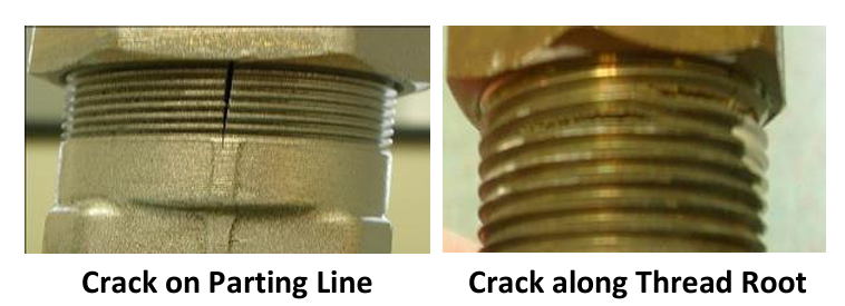
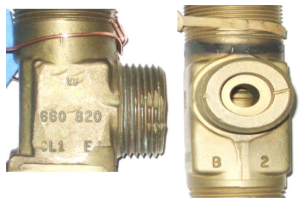
A. Inspect the valve body for cracks, mainly along the forging parting line as well as in the area of the packing nut (6) threads. (Refer appendix D of pamphlet 17 for more details)
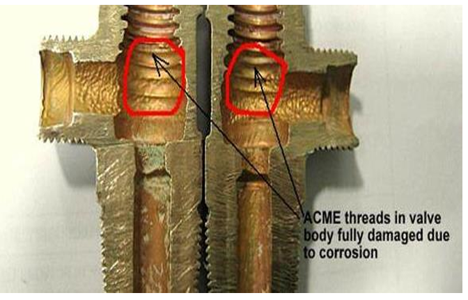
B. Check internal bores & ACME threads for gross corrosion, material loss or material build-up. In case of material build-up use thread tap (item code – TAP0013) to clean the threads. Use plain plug gauge (item code LM00066) & thread plug gauge (item code – TGSS081) to check if internal ACME thread is within specification. The threads closest to the body seat are the most susceptible to corrosion. Loss of these threads can lead to unengaged threads when the valve is closed, resulting in a “spinner” thread loss & should be rejected.
C. The sharp edge of valve body seat will become bevelled with repeated closing requiring more & more torque to close the valve. Recondition seat using seat cutter (item code – SC00001) to restore sharp edge by refacing. Due to the smaller orifice of cylinder valve compared to ton container valve, the seat cutter allows for higher cutting depth on cylinder valve compared to ton container valve. Use depth gauge for cylinder valve (item code – CG00001) & ton container valve (item code – TG00001) to ensure the seat is not cut beyond the allowable limit.
D. If stems (2) are also machined, use Combination gauge (item code – CG/TG/2) to ensure the refacing limit of Chlorine valve body assembled with the reconditioned stem is not exceeded.
E. The external threads on valve body (inlet, outlet, & packing nut end) should be examined for corrosive damage, heavy wear, & material loss. Use Rethreading dies for outlet (item code – RDHS004) & packing nut (6) threads to remove material build up. Re-died outlet threads should be subsequently checked by plain thread ring “GO” & “NO GO” gauges (item code – LM00009) and thread ring “GO” & “NO GO” gauges (item code – TGSS005)
F. The valve outlet sealing face should be checked for nicks & crack & refaced if required.
G. Inspect inlet threads visually & use soft wire brush to remove burrs.
Components
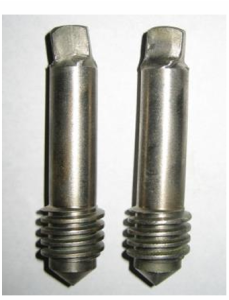
A. Check stem (2) for twisting due to excessive torque in both opening & closing direction. Twisted stem indicates that the valve seat may be damaged. Check stem shank for roughness, scratches & nick. Replace stems with above defects.
B. Inspect packing (4) for wear & discard one or both rings if found in unusable condition.
C. Inspect components for structural cracks, gross corrosion & other damages.
D. Inspect fusible plug (9) in cylinder valve for signs of leakage, extrusion of fusible metal, corrosion &/or damage. Do not remove fusible plug from valve body (1) unless it is defective.
iii. Assembly of valve
- Use only cleaned parts for assembly.
- Apply minimum 200 mg Krytox GPL 225 or any equivalent Chlorine compatible lubricant on valve stem (2) threads & shank.
- Screw in fully valve spindle into valve body (1).
- Insert packing collar (3) with conical face upwards to rest on valve body counter bore. 5. Push packings (4) over stem shank to rest on packing collar. Ensure the bevelled side of the packings are on the top & bottom face respectively.
- Insert packing gland (5) ensuring conical face downward.
- Screw in packing nut (6) in valve body. Clamp valve body assembly in bench vice between soft pads.
- Tighten the packing nut in clockwise direction using suitable torque wrenches (Tekno Valves item code – WR-EN-1) at 40 ft-lb.
- Rotate stem using twisted wrench to ensure smooth movement.
- Tighten fusible plug (9) (if applicable) in clockwise direction using PTFE tape or any Chlorine compatible thread sealant like Kyrtox TS4 at 12-15 ft-lb.
iv. Testing of valve
- Connect the assembled valve inlet to oil free dry air or nitrogen at 500 psig.
- Plug the valve outlet using outlet cap (8) & open the valve in anti-clockwise direction. 3. Check for leakage past the packings (4) using ammonia free soap solution for one minute.
- Tighten the packing nut (6) in clockwise direction up to 40 ft-lb in case of gland leakage. 5. Close the valve by tightening the stem (2) at maximum 30 ft-lb in clockwise direction. 6. Check leakage through the valve outlet & fusible plug (9) for one minute. 7. After completion of testing, remove the outlet cap & dry the valve thoroughly.